Beach House Morocco
Villa
Fuaim na Mara
"The Sound of the Sea"
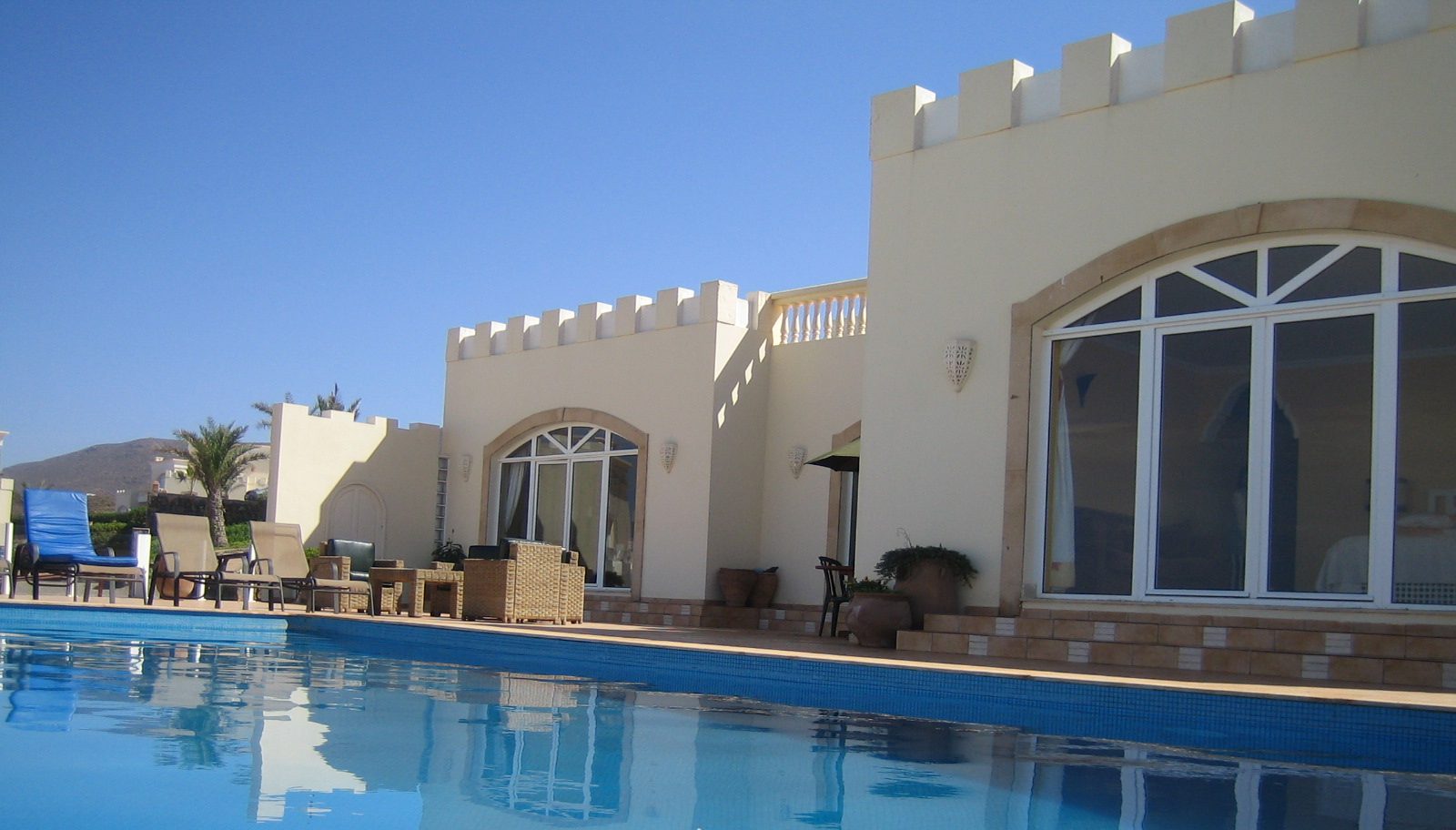
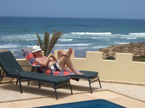
This stunning private Moroccan villa is situated below the foothills of anti Atlas Mountains in Southern Morocco facing out to the Atlantic sea.
Available for rent. Please us the contact form to get in touch
240
Sq Metres
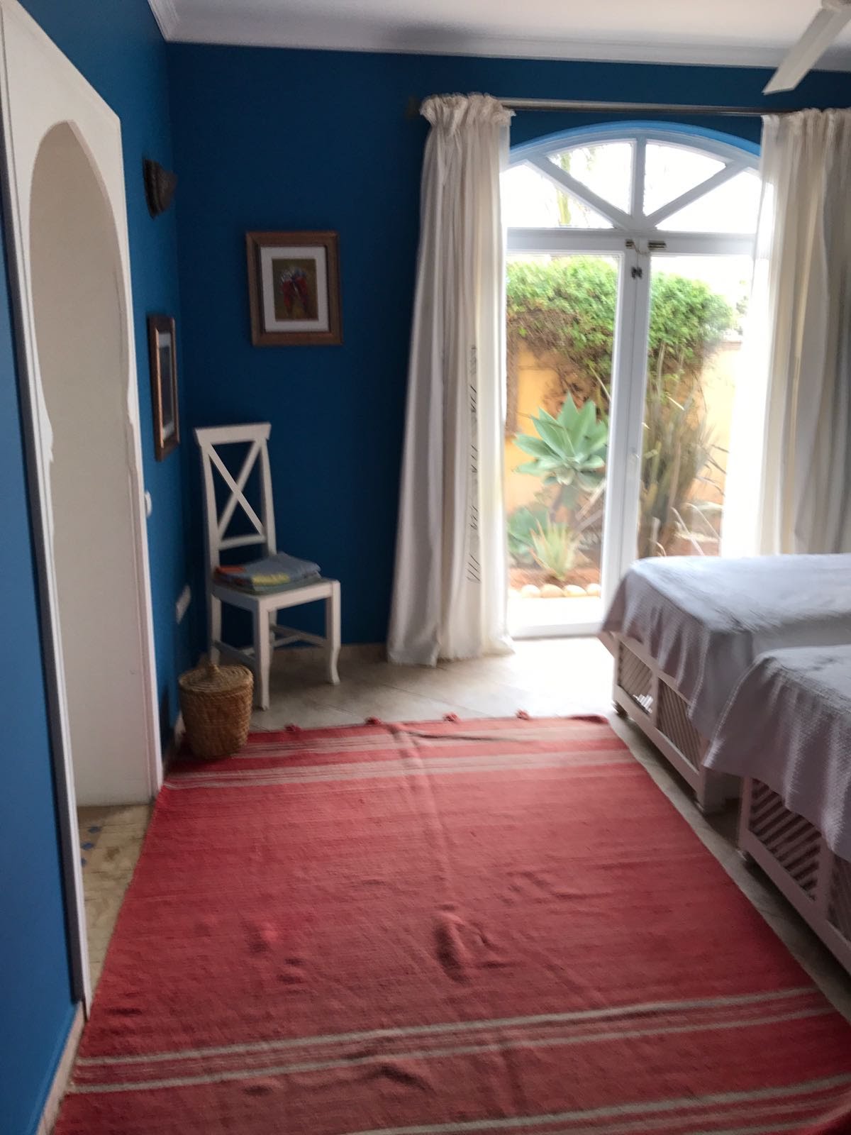
8
Sleeps

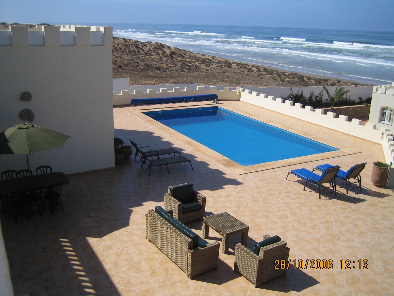
The Pool
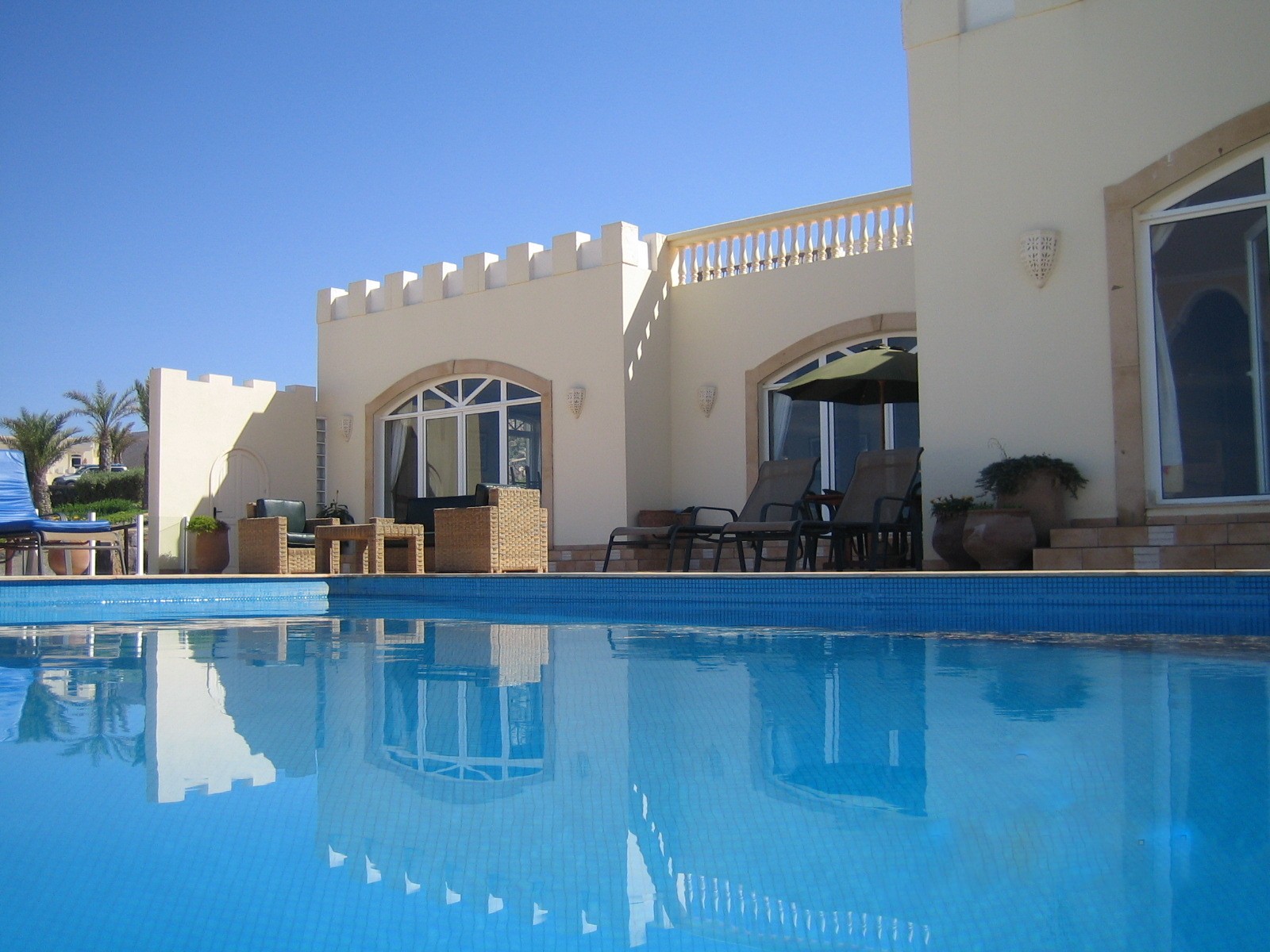
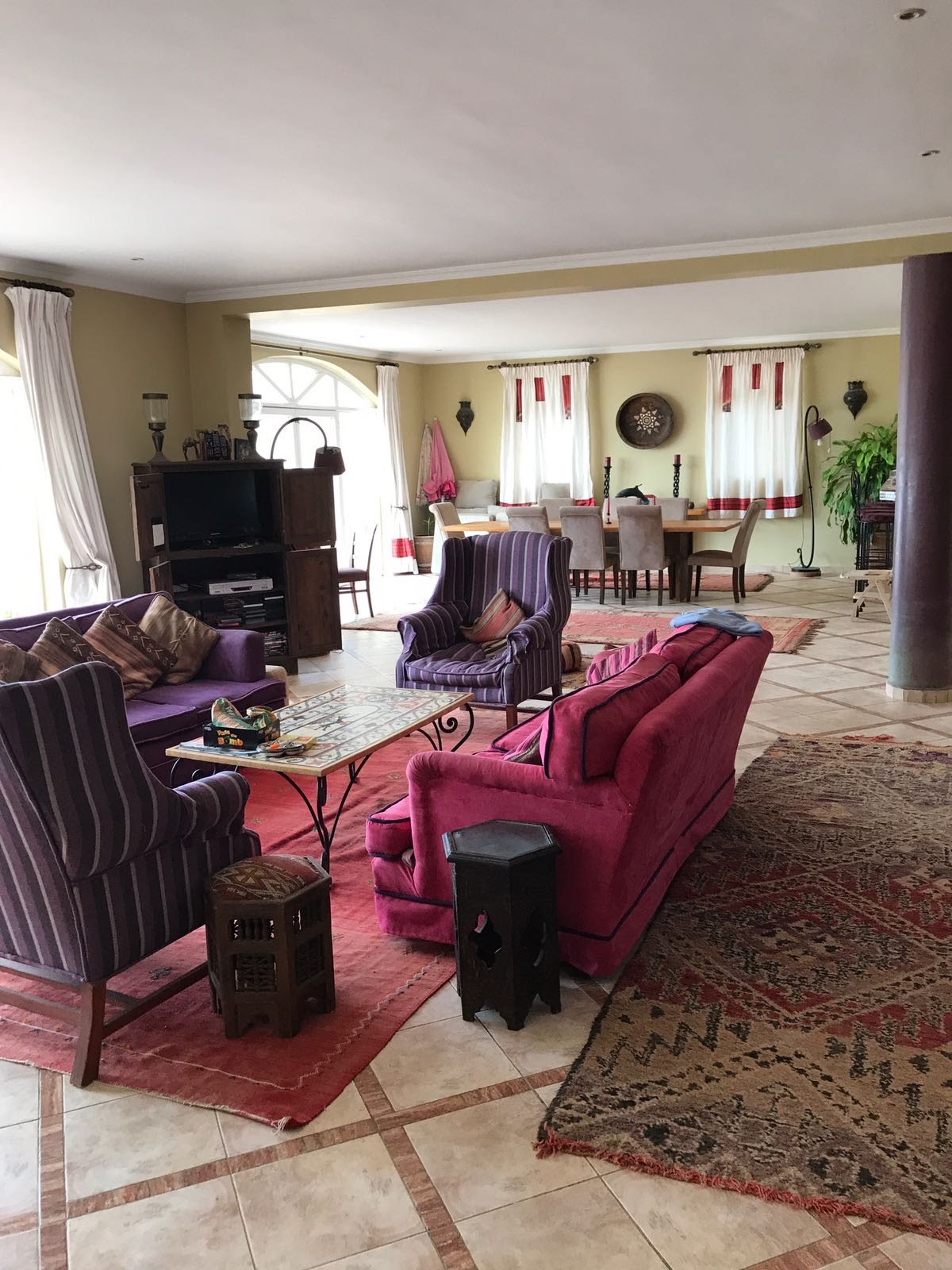
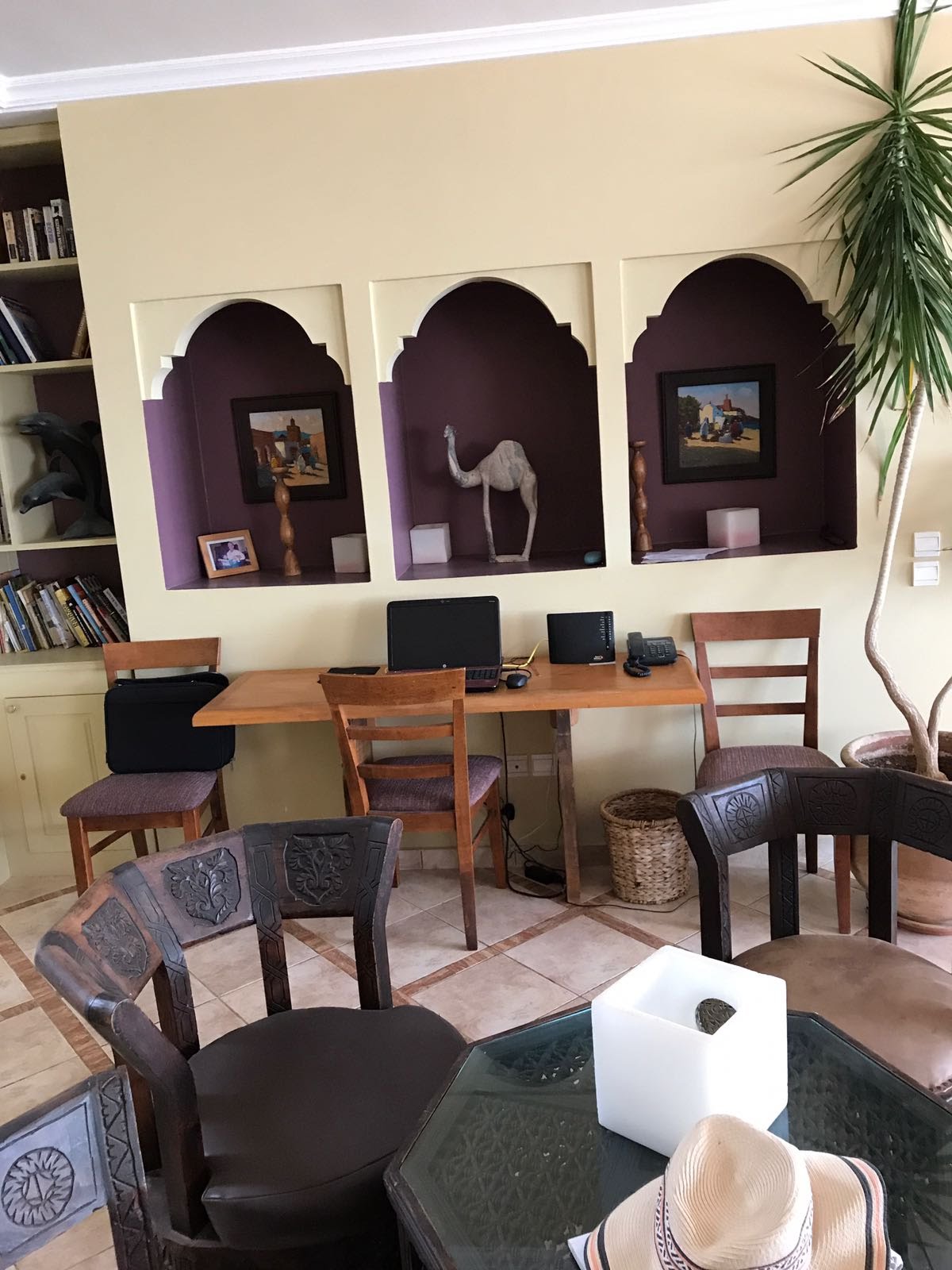
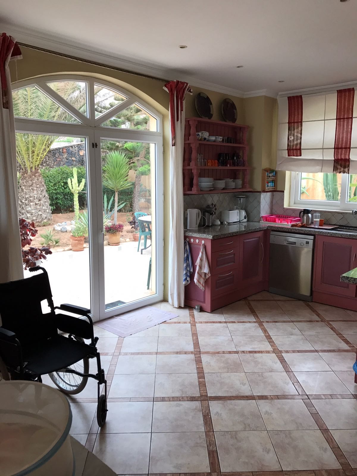
The Villa
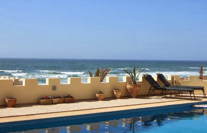
The Sea